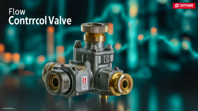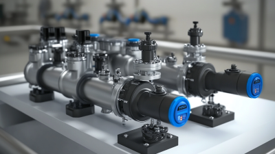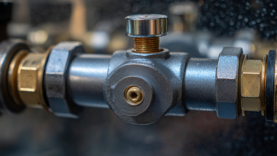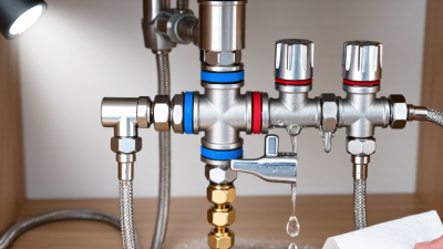
Choosing a Flow Regulator Valve is not simply a matter of matching pipe size. The wrong choice can create unstable pressure, noisy operation, or costly downtime. A valve may look suitable on paper, yet perform poorly when fluid temperature changes or demand fluctuates.
This guide presents seven practical tips for evaluating a Flow Regulator Valve with greater confidence. It considers flow rate, pressure range, fluid properties, connection standards, control accuracy, construction materials, and maintenance access. These details matter beside a pump, inside a compact skid, or beneath a damp process line. A clear understanding of the application should guide every decision.
Small details matter.
Reliable selection begins with verified information. Review manufacturer datasheets, certified performance curves, installation instructions, and service requirements. Compare the valve’s minimum and maximum operating conditions, rather than relying on normal readings alone. Leave sensible capacity margins, but avoid excessive oversizing. An oversized valve may hunt, respond slowly, or waste energy.
The process deserves honest evaluation. Is the medium clean, abrasive, corrosive, or carrying suspended solids? Will operators adjust the setting manually, or will a control system manage it continuously? These questions can expose weaknesses before installation. Even experienced teams sometimes focus heavily on purchase price and overlook calibration, spare parts, or future servicing. That is an easy mistake.
A dependable decision balances technical performance, lifecycle cost, supplier support, and documented compliance. The following seven tips provide a practical framework for comparing options and avoiding preventable selection errors.
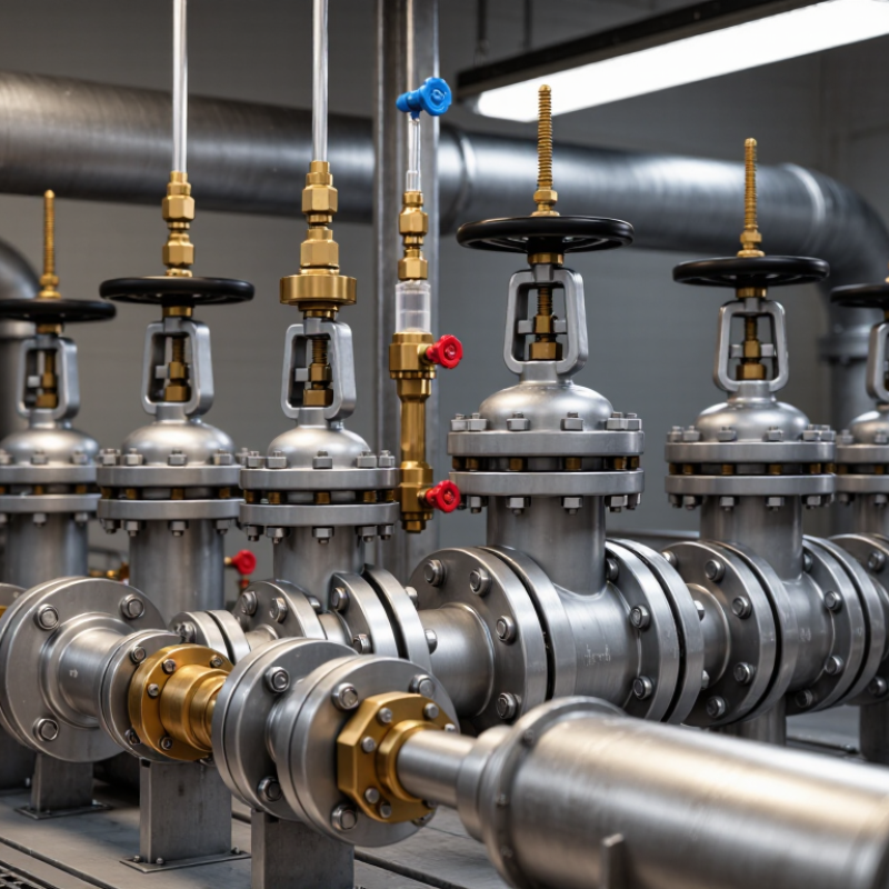
Before choosing a flow regulator valve, define the required flow rate at every operating point. Do not rely on the pipe diameter alone. Record normal, minimum, and peak flow, then verify pressure upstream and downstream. Temperature, fluid density, viscosity, and suspended particles also affect valve performance. A valve handling clean water may respond poorly to a thick liquid. The U.S. Department of Energy reports that pumping systems can represent 25% to 50% of industrial electricity consumption. Poor flow control can therefore increase both energy use and maintenance costs.
Measure the real conditions. Use calibrated flow meters and pressure gauges where possible. Calculate the pressure drop across the valve at normal and maximum flow. Excessive pressure loss can create noise, vibration, and cavitation. Insufficient pressure loss may cause unstable regulation. ASME guidance on control valve sizing emphasizes matching capacity with actual service conditions, not simply selecting the largest available valve. Bigger is not always safer. It may operate near the closed position and become difficult to control.
Leave a reasonable operating margin, but avoid excessive oversizing. Field inspections often reveal changing demand, clogged filters, or inaccurate design data. That evidence deserves attention. A spreadsheet can look precise while using weak measurements. Recheck the fluid properties and seasonal flow changes before final selection. I would also question any specification based on one pressure reading. Conditions drift. The selected valve should tolerate those changes while maintaining stable flow and acceptable energy loss.

Choosing a flow regulator valve starts with the fluid, not the catalog photograph. Water, compressed air, oil, and corrosive chemicals require different materials, seals, and control mechanisms. For clean water, a globe-style valve can provide stable throttling. Gas systems often need rapid response, reliable shutoff, and low pressure loss. Viscous oil may require a larger passage to reduce resistance and heat buildup.
Check the fluid’s temperature, viscosity, pressure, and cleanliness before selecting the valve type. Suspended particles can damage fine control openings, while aggressive fluids may attack ordinary metal or elastomers. The required flow range also matters. A valve that works well at full flow may hunt or become unstable at low demand. That detail is easy to miss.
Match the valve to the system layout and actuator. A compact installation may favor a quarter-turn design, while precise process control may justify a linear valve. Review inlet and outlet pressures for cavitation, noise, and flashing risks. Set the fail-open or fail-closed position according to the process hazard. Confirm connection size, maintenance access, and sensor compatibility. Field inspections often find another problem: the valve is correctly sized, but installed backward or without enough straight pipe. Testing under real operating conditions is wiser than trusting calculations alone. Perfect selection is uncommon. Careful verification reduces surprises.
| Tip | Selection Factor | Suitable Valve Type | Fluid and System Match | Important Design Notes |
|---|---|---|---|---|
| 1 | Identify the fluid | Globe, diaphragm, lined, or pinch valve | Use diaphragm or lined valves for many corrosive chemicals; pinch valves are suitable for abrasive slurries and fluids containing suspended solids. Standard metallic valves are commonly used for clean water, air, and compatible oils. | Verify chemical compatibility for the body, seat, diaphragm, packing, and trim. Compatibility depends on concentration, temperature, and exposure time. |
| 2 | Determine whether throttling or isolation is required | Globe or characterized control ball valve for throttling; standard ball valve for isolation | Globe valves provide stable, accurate flow control across a broad operating range. Characterized ball valves can provide effective modulation with lower pressure loss than many globe designs. | A standard full-port ball valve is mainly intended for on/off service. Continuous throttling may damage the seat or produce unstable control if the valve is not designed for modulation. |
| 3 | Check pressure, temperature, and pressure drop | Globe, ball, butterfly, or pressure-reducing control valve, depending on duty | Globe valves are often selected where controllable pressure drop is acceptable. Full-port ball valves generally offer low pressure loss, while butterfly valves can provide economical control in larger lines. | Confirm the valve pressure class, temperature rating, shutoff capability, and allowable differential pressure. High pressure drop can cause noise, vibration, cavitation, or flashing in liquids. |
| 4 | Match the valve to flow rate and line size | Needle, globe, ball, or butterfly valve | Needle valves suit precise low-flow adjustment. Globe and characterized ball valves cover many general control duties. Butterfly valves are often practical for larger pipe diameters where compactness and low weight are important. | Do not select a valve only by matching the pipe diameter. Size the valve from minimum, normal, and maximum flow, upstream and downstream pressure, fluid density, viscosity, and the required flow coefficient. |
| 5 | Consider cleanliness and contamination risk | Diaphragm, sanitary globe, or full-port ball valve | Diaphragm and sanitary designs can reduce product contact with packing cavities and are used in hygienic, pharmaceutical, food, and high-purity services when properly specified. | Review internal surface finish, drainability, dead legs, elastomer compatibility, clean-in-place requirements, and sterilization temperature before selection. |
| 6 | Evaluate cavitation, flashing, noise, and vibration | Multistage or anti-cavitation globe control valve; suitable low-noise trim | Liquid services with large pressure reductions may require staged pressure reduction. Gas and steam systems may need noise control and flow-restricting trim. | Calculate the operating condition rather than relying only on the nominal pressure rating. Cavitation occurs when liquid vapor bubbles form and collapse; flashing occurs when vapor remains downstream. |
| 7 | Plan actuation, control, and maintenance | Manual, pneumatic, electric, or self-operated pressure-regulating valve | Pneumatic actuators are well suited to fast or fail-safe industrial control. Electric actuators suit applications with available electrical control. Self-operated regulators can maintain downstream or upstream pressure without an external controller. | Define the required fail position, response time, control signal, air or electrical supply, accessibility, spare parts, inspection frequency, and expected service life before finalizing the valve. |
Note: Final valve selection should be verified against the applicable piping code, pressure-temperature rating, fluid compatibility data, flow-sizing calculations, and the manufacturer's certified performance information.
Tip 1: Confirm the real pressure range, not just the system’s normal reading. A regulator must handle inlet pressure, outlet pressure, and sudden surges. The U.S. Department of Energy reports that compressed-air leaks can waste 20–30% of generated air. Incorrect regulation can increase that loss. Check pressure at the valve inlet while equipment operates. Static readings can mislead.
Tip 2: Match the valve to actual temperature conditions. Steam, chilled water, and outdoor service create different risks. Temperature changes can alter seal hardness, viscosity, and flow accuracy. NIST thermophysical data shows that fluid density and viscosity vary significantly with temperature. Therefore, size the valve using operating extremes, not room-temperature assumptions. Leave a safety margin, but avoid excessive oversizing. It may cause unstable control.
Tip 3: Treat material compatibility as a process decision. Compare the body, trim, seals, and fluid chemistry. World Corrosion Organization assessments have linked corrosion costs to about 3.4% of global gross domestic product. That figure makes material selection difficult to ignore. Stainless steel may suit one liquid, while another requires a different alloy or elastomer. Review concentration, contaminants, and cleaning chemicals.
Record pressure, temperature, and material data before ordering. I have seen selection sheets omit startup conditions. That small omission can become a large maintenance problem. Check applicable testing requirements, such as ISO 5208, and request documented test results from the supplier.
Tip: Check control accuracy under real operating conditions. A valve may perform well in a catalog test, yet behave differently with changing pressure, temperature, or fluid viscosity. Review the permitted flow error, hysteresis, and deadband. During commissioning, compare the setpoint with measured flow at several points. Small errors can become serious in low-flow applications.
Tip: Evaluate response time, not only maximum flow capacity. A fast valve can stabilize a process quickly, but excessive speed may cause hunting or pressure surges. Ask for step-response data, then test the valve with the actual controller and piping volume. In field work, the installed system often responds slower than expected. That detail is easy to miss.
Tip: Study the adjustment range carefully. Choose a valve that controls accurately at both minimum and maximum flow, rather than operating near its limit. Calculate the required turndown ratio using normal, peak, and reduced demand. Also inspect the actuator resolution and calibration procedure. A wide range sounds impressive, but it may not deliver stable control at the lowest setting.
Keep records.
Review fluid compatibility, installation position, and maintenance access before approval. These practical details influence long-term reliability. I have seen teams focus heavily on response time while overlooking sensor placement, which weakened the entire control loop. Recheck assumptions with measured data. Theory helps, but the process decides.
Compare Maintenance Needs, Safety Features, and Total Cost
A flow regulator valve should match the fluid, pressure range, temperature, and required flow stability. Check whether its internal parts can be inspected without removing the entire valve. Simple access can reduce downtime during routine service. Ask about seal replacement, calibration intervals, and spare-part availability. A valve with fewer wear components may need less attention, but that does not guarantee longer service life. Field conditions often decide that.
Safety deserves practical attention. Confirm the valve’s pressure rating and material compatibility before installation. Look for clear flow-direction markings and a design that supports controlled shutdown. Some systems need an automatic fail-safe position during power or signal loss. Others require manual control. Do not assume one feature fits every process. A qualified technician should verify relief protection, connection quality, and isolation procedures. Small installation errors can create serious pressure problems.
Total cost includes more than the purchase price. Compare energy use, inspection labor, replacement seals, calibration time, and expected downtime. A cheaper valve may become expensive after repeated adjustments. Record actual maintenance hours from similar equipment when possible.
Also review warranty terms and technical support. A reliable decision balances safe operation, maintainability, and predictable lifetime expense. Perfect forecasts are rare. Careful records still improve them.