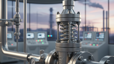
Choosing the right Pressure Valve starts with one question: what must the valve control? A relief valve protects equipment from excess pressure. A reducing valve maintains lower downstream pressure. A control valve adjusts flow as operating conditions change. These roles are not interchangeable. The wrong choice can cause unstable pressure, poor performance, or unnecessary wear.
For a transparent editorial example, composite pressure-systems specialist Jordan Lee offers this reminder: “Match the valve to the operating conditions, not just the pipe size.” This is an illustrative quotation, not a verified statement from a real expert. In practice, selection begins with the fluid, normal and maximum pressure, temperature range, required flow, and acceptable pressure drop. A small detail matters: a valve that works well at steady flow may respond poorly to frequent demand changes. Check the manufacturer’s sizing data and installation guidance, rather than relying on a catalog headline.
Look closely at materials and connections, too. Water, steam, and corrosive process fluids place different demands on valve bodies and seals. Confirm the pressure rating, connection type, and maintenance access. A cramped installation can turn a simple inspection into a difficult job. There is no perfect choice. Real systems have compromises, and early assumptions sometimes need review. The practical goal is a Pressure Valve that performs reliably within its intended limits and can be serviced safely.
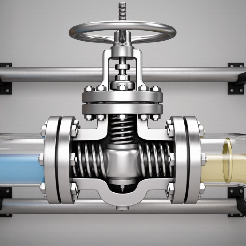
Before choosing a pressure valve, write down normal, minimum, and maximum operating pressure—not just the number on the equipment label. Include startup, shutdown, and credible upset conditions. A valve sized for normal flow alone may struggle during a surge. Record the fluid, temperature, viscosity, and required flow range; these details affect capacity and material selection. Small details matter. The U.S. Department of Energy’s Improving Pumping System Performance sourcebook reports that pumping systems can account for 25–50% of energy use in some industrial plant operations. That range is a reminder: excess pressure drop can carry a real operating cost.
Define the safety function separately. A control valve regulates process conditions; a relief valve protects equipment when pressure rises beyond its permitted limit. Confirm the required set pressure, relieving capacity, discharge conditions, and safe failure position against the system design and applicable engineering codes. Check the valve’s pressure-flow curve across expected conditions, not at one convenient point. A common weak spot is treating the stated maximum pressure as the only hazard; blocked outlets or rapid temperature changes may alter the scenario. That is not enough. Document assumptions, then have a qualified engineer review them. Some operating data will be incomplete; flag it rather than quietly treating an estimate as fact.
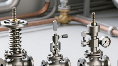
Before choosing a pressure valve, define the job it must perform. A relief valve protects equipment by opening when pressure exceeds a set limit. A pressure-reducing valve maintains lower downstream pressure. A back-pressure valve holds pressure upstream. They are not interchangeable. On a steam line, for example, confusing pressure control with overpressure protection can leave equipment exposed to unsafe conditions.
The U.S. Department of Energy’s 2012 Improving Steam System Performance: A Sourcebook for Industry estimates that steam systems account for about 30% of U.S. industrial energy use. That figure is a useful reminder: valve function affects both equipment protection and operating performance. Record the normal inlet and outlet pressures, required flow, fluid, temperature, and pressure fluctuations before specifying a valve. Then check whether the valve needs to relieve, regulate, or isolate pressure. Small details matter.
A tidy specification can still miss real operating conditions. A valve sized for normal flow may respond poorly during startup or sudden demand changes. I would verify the duty against operating data, not just a nameplate reading. For relief applications, consult the applicable engineering code and have qualified personnel confirm sizing and set pressure. Pressure control is not a guess.
Pressure valves serve different purposes. Compare each valve’s primary function to identify the type that matches your system’s needs.
How to read the chart: A value of 1 indicates a primary intended function; 0 means it is not the valve’s primary purpose. This is a general comparison, not a substitute for checking a specific valve’s specifications or applicable safety requirements.
Pressure valves may look alike, but they control different parts of a system. A pressure-reducing valve throttles flow to maintain a lower downstream pressure. A relief valve opens when inlet pressure exceeds its set point, allowing excess fluid to leave through a designated path. A back-pressure regulator restricts flow to maintain pressure upstream. Not the same job.
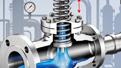
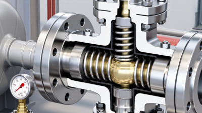
Direct-acting valves use pressure against a spring or diaphragm to move the valve element. Their simple mechanism can respond quickly, though performance may vary as flow changes. Pilot-operated valves use a smaller pilot valve to control a larger main valve. They can handle higher flows with steadier control, but add components that need attention. That matters.
Compare more than the valve label. Check operating pressure, expected flow, fluid type, temperature, and how much pressure drop the system can tolerate. For example, a small pump line may suit a direct-acting regulator, while a high-flow process line may need a pilot-operated design. The neat chart can mislead; real systems fluctuate. Confirm the operating range against technical data, and have a qualified engineer review safety-critical pressure protection.
A pressure valve is not chosen by its pressure rating alone. Start with the fluid. Water, steam, oil, and chemical solutions can affect valve bodies, trim, and seals differently. Check the material’s compatibility at the expected temperature, not just at room temperature. Stainless steel may suit some corrosive settings, while a compatible seal can matter just as much. Small details matter.
Then inspect the connection. Match the valve to the pipe’s thread or flange standard, size, and pressure class. A connection that almost fits is still a poor fit; forced alignment can strain the joint or distort a seal. Consider vibration and pipe loads, too. These are easy to overlook on a tidy drawing.
Operating conditions complete the picture. Note normal pressure, maximum pressure, temperature swings, flow rate, and frequent start-stop cycles. Pressure spikes can exceed the steady reading on a gauge, so review how the system behaves during startup and shutdown. Leave room for uncertainty: real operating conditions may differ from the design assumptions. I still think the catalog rating gets too much attention. Verify the selected valve’s limits and intended service with its technical documentation or a qualified engineer.
A pressure valve should match the real operating conditions, not just the pipe size. Record the fluid, normal and maximum pressure, temperature, and expected flow. For a relief valve, confirm its set pressure and required discharge capacity. Check inlet losses and outlet backpressure; either can affect performance. Small details matter. A valve selected from a rough estimate may appear suitable on paper yet fail to protect equipment during an upset. A neat spreadsheet can still hide a bad assumption.
Verify the applicable pressure-equipment and valve standards, including the correct edition and requirements for the installation location. Compare the valve’s certified ratings with the system’s design conditions, and keep documentation traceable to the selected model and materials. Then review maintenance access, inspection intervals, and test procedures before purchase. Ask how the valve can be isolated and removed safely, and whether deposits or corrosion could restrict moving parts. Set inspection timing from the manufacturer’s instructions, service conditions, and inspection findings; one fixed interval will not fit every plant. Record test results, repairs, and changes to operating conditions. If the duty is unusual, have a qualified engineer review the sizing and assumptions. That assumption deserves review.
| Selection Step | Information to Verify | Practical Guidance | Relevant Standard or Maintenance Check |
|---|---|---|---|
| 1. Identify the valve function | Determine whether the application needs a pressure safety/relief valve for overpressure protection or a pressure-reducing/control valve for normal pressure regulation. | Do not treat a control valve as a substitute for a code-required pressure-relief device. Confirm the protected equipment and credible overpressure scenarios. | Review the applicable vessel or piping code and the facility’s overpressure-protection design basis. |
| 2. Establish the pressure basis | Record the protected equipment’s maximum allowable working pressure (MAWP), normal operating pressure, required set pressure, and any permitted accumulation or overpressure. | Set pressure and allowable pressure rise depend on the governing code and scenario. Check the equipment nameplate and design documents; do not select a set pressure from normal operating pressure alone. | For pressure vessels, check the applicable ASME Boiler and Pressure Vessel Code requirements, including Section VIII where applicable. |
| 3. Calculate required relieving capacity | Identify the governing relief case and required mass or volumetric flow, such as blocked outlet, external fire exposure, thermal expansion, or utility failure. Gather fluid composition and relevant operating properties. | Size the valve for the controlling scenario using applicable calculation methods. Gas/vapor, steam, and liquid service require different inputs; account for inlet and outlet piping effects. | API 520 addresses sizing and selection of pressure-relieving devices; API 521 provides guidance for pressure-relieving and depressuring systems. Confirm which editions and requirements apply to the project. |
| 4. Select the valve type and materials | Check phase, temperature, corrosiveness, toxicity, viscosity, solids, polymerization risk, and whether the discharge system is open or connected to a header. | Evaluate conventional, balanced, or pilot-operated designs against the actual backpressure and service conditions. Confirm body, trim, seal, and connection materials are compatible. | For applicable flanged pressure-relief valves, API 526 covers standardized face-to-face dimensions and orifice designations. Verify the pressure-temperature rating for the selected materials and flange class. |
| 5. Check inlet pressure loss | Calculate pressure loss through the inlet piping and fittings at the required relieving flow, including the effects of length, diameter, and configuration. | A commonly used API 520 screening recommendation for a conventional spring-loaded valve is to keep non-recoverable inlet pressure loss at or below 3% of set pressure. Confirm applicability for the specific valve, service, and design. | Review API 520 guidance and the valve manufacturer’s installation limits. Excessive inlet loss can contribute to unstable operation or chattering. |
| 6. Evaluate outlet backpressure | Determine superimposed and built-up backpressure over the full range of operating and relief scenarios, including header pressure and discharge-line losses. | Compare calculated backpressure with the selected valve design’s allowable limits. Backpressure can affect capacity and opening or closing behavior; use the applicable correction method. | Use API 520 and API 521 guidance as applicable, and check the certified capacity and backpressure limits for the specific valve configuration. |
| 7. Confirm connection and rating | Verify inlet and outlet size, facing, pressure class, material specification, installation orientation, and compatibility with connected piping. | Do not assume pipe size alone determines valve capacity. Confirm the selected orifice/capacity, pressure-temperature limits, and piping loads against the design documents. | For process piping, identify the governing code, such as ASME B31.3 where applicable. Check applicable flange standards and project specifications. |
| 8. Plan inspection and maintenance | Document service severity, corrosion or fouling risk, leak history, test results, operating conditions, and any relevant regulatory inspection requirements. | Set inspection and test intervals using applicable regulations, service risk, operating experience, and the asset integrity program. There is no single interval suitable for every installation. | Keep records of set-pressure tests, repairs, parts, and certification. API 527 addresses seat tightness testing for pressure-relief valves; follow the applicable procedure and acceptance criteria. |
| 9. Complete a final design review | Review calculations, certified capacity, set pressure, materials, inlet and outlet piping, discharge destination, installation details, and maintenance access. | Have the selection and relief-system design checked by qualified personnel. Record assumptions and confirm all equipment and piping limits are protected. | Apply the jurisdictional code, adopted standard editions, and site procedures. Resolve any conflict between design documents and field conditions before commissioning. |
Note: Final valve sizing, set pressure, code compliance, and maintenance intervals must be confirmed for the specific equipment, service conditions, jurisdiction, and applicable standard editions.