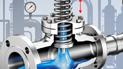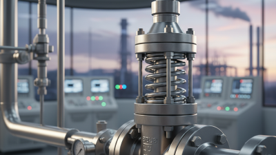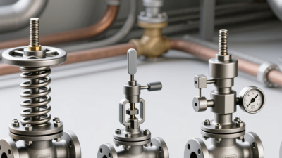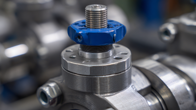
Choosing the right Relief Valve is a process-safety decision, not a simple catalog exercise. A valve may look suitable on a drawing yet fail under real operating conditions. Pressure, temperature, fluid phase, corrosion, backpressure, and discharge routing all affect performance. A small mismatch can leave a vessel exposed when the process changes suddenly.
The American Petroleum Institute’s API 520 and API 521 publications provide widely used guidance for sizing, selection, installation, and disposal-system design. ISO 4126-1 also defines requirements for safety valves protecting equipment from excessive pressure. These documents emphasize credible overpressure scenarios, not merely normal operating data. The U.S. Chemical Safety and Hazard Investigation Board’s BP Texas City investigation report recorded 15 fatalities and 180 injuries in 2005. It showed how weak safeguards and poor hazard management can magnify a process upset. A Relief Valve is only one protection layer.
Selection should begin with evidence from the process. Confirm the set pressure, relieving temperature, required capacity, fluid properties, and allowable accumulation. Then review built-up backpressure, inlet pressure loss, two-phase flow, and maintenance access. Field experience matters here. A valve installed beside a vibrating pump may behave differently from one tested in a quiet workshop. That detail is easy to overlook.
There is no universal best valve. Spring-loaded, pilot-operated, and balanced-bellows designs each have limitations. Product data must be checked against recognized standards and manufacturer test certificates. Even experienced engineers can miss a changing operating case. That is why independent review, documented calculations, and periodic inspection remain essential when choosing the right Relief Valve.
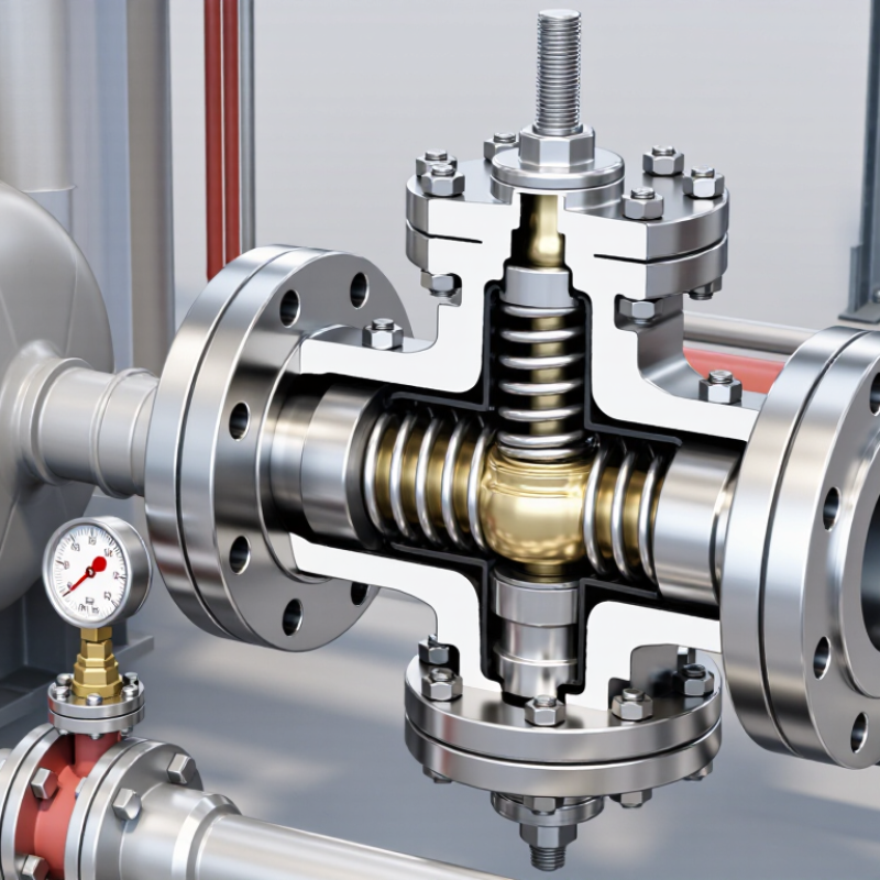
Before choosing a relief valve, define the pressure problem it must control. Is the system protecting against blocked discharge, thermal expansion, fire exposure, or a failed control device? Each scenario can produce different pressure behavior. A valve selected without this definition may open too late or discharge too often.
In field reviews, I check the protected equipment, normal operating pressure, maximum allowable working pressure, and possible pressure sources. The set pressure should protect the weakest approved component, not merely match the pump rating. For liquid service, thermal expansion can create dangerous pressure in a trapped section. For gas service, flow capacity and compressibility require closer attention. Discharge piping also matters. Excessive backpressure can reduce capacity and affect opening performance.
Look beyond the valve body. Confirm the fluid, temperature range, corrosion risk, inlet losses, outlet routing, and maintenance access. A relief valve is part of a pressure-protection system. It is not an isolated purchase. I have seen installations with correct set pressure but undersized discharge lines. That detail was easy to miss. It should not have been. Ask when the valve must open, how long it may relieve, and where the released medium can go safely. Review calculations against current engineering standards, then record the assumptions. Real systems change, and old assumptions can become unreliable.
| System Area | Relief Valve’s Role | Typical Pressure Relationship | Key Selection Dimensions | Practical Engineering Guidance |
|---|---|---|---|---|
| Pressure Protection Vessels and piping |
Protects pressure-containing equipment from exceeding its allowable pressure limit during abnormal or upset conditions. | Set pressure is normally selected at or below the protected equipment’s allowable working pressure. | Allowable working pressure, design pressure, set pressure, accumulation, relieving pressure, and required relieving capacity. | Confirm the weakest protected component. The valve must discharge enough fluid to stop pressure from continuing to rise during the governing overpressure scenario. |
| Thermal Expansion Blocked-in liquid lines |
Relieves pressure created when a trapped liquid expands because of heat input or rising ambient temperature. | Relieving flow is usually small, but liquid pressure can rise rapidly in a fully blocked-in section. | Liquid service, thermal expansion rate, fluid compressibility, trapped volume, temperature range, and discharge routing. | Do not size a thermal-relief valve as though it were protecting a large vessel against fire exposure. Verify that the blocked-in volume and heat source are correctly identified. |
| Gas and Vapor Compressible service |
Limits pressure in gas, steam, air, or vapor systems by releasing excess mass flow to a safe location. | Capacity depends strongly on upstream relieving pressure, relieving temperature, molecular weight, compressibility, and flow regime. | Orifice capacity, backpressure, inlet pressure loss, outlet piping, temperature, viscosity, and discharge coefficient. | Use the actual relieving conditions rather than normal operating conditions. For gas service, check whether the flow is choked at the valve nozzle. |
| Liquid Service Pumps and process lines |
Protects pumps, heat exchangers, hydraulic circuits, and liquid-filled piping from dead-heading or excessive pressure. | The set pressure must account for pump shutoff head, system resistance, and the pressure rating of downstream equipment. | Liquid density, viscosity, required flow rate, differential pressure, cavitation risk, inlet pressure loss, and backpressure. | A valve suitable for gas service may not be suitable for liquid service. Select and size the valve using liquid-capacity methods and verify stable operation. |
| Fire Exposure Vessels containing fluids |
Provides emergency pressure relief when external fire adds heat and causes rapid vapor generation or liquid expansion. | The relieving load can be substantially higher than normal process flow and is based on credible heat input. | Wetted surface area, insulation, fire exposure assumptions, fluid properties, vapor generation, and required emergency capacity. | Treat fire exposure as a separate relief scenario. Consider whether the relief device, discharge system, and vessel design can safely handle the resulting two-phase flow. |
| Vacuum Protection Low-pressure equipment |
Prevents vessel collapse or structural damage when internal pressure falls below the design vacuum limit. | A vacuum breaker opens on inward pressure differential rather than on excessive positive pressure. | Vacuum set point, air or inert-gas inflow, venting rate, external pressure rating, contamination control, and corrosion resistance. | A positive-pressure relief valve does not automatically provide vacuum protection. Evaluate pump-out, cooling, condensation, and steam-out scenarios separately. |
| Pressure Control Continuous process operation |
Maintains a target pressure by modulating flow during normal operation rather than acting only as an emergency safety device. | Operating pressure should remain sufficiently below the relief set pressure to prevent unnecessary lifting or simmer. | Control range, response speed, flow turndown, allowable leakage, backpressure variation, and process stability. | Use a pressure-control valve for routine regulation when appropriate. A safety relief valve should not be used as the primary control element for normal pressure management. |
| Backpressure Discharge system |
Releases fluid while remaining functional when the outlet is connected to a header, flare, scrubber, or recovery system. | Built-up backpressure is generated during discharge; superimposed backpressure exists before the valve opens. | Constant or variable backpressure, balanced or conventional design, outlet pressure losses, reaction forces, and discharge temperature. | Calculate the complete inlet and outlet pressure-loss profile. Excessive backpressure can reduce capacity, cause instability, or change the valve’s effective set pressure. |
| Fluid Compatibility Corrosive or contaminated media |
Maintains reliable pressure protection while resisting corrosion, erosion, plugging, and deposits caused by the process fluid. | Material performance must remain acceptable at normal, relieving, startup, shutdown, and cleaning conditions. | Chemical compatibility, temperature, concentration, solids content, phase change, elastomer compatibility, and surface finish. | Select body, trim, spring, bellows, seals, and discharge materials as a complete system. Account for corrosion allowances and possible crystallization or polymerization. |
| Maintenance and Testing Long-term reliability |
Allows inspection, testing, repair, and replacement while preserving the intended protection function. | Performance must remain within the specified tolerance over the inspection interval and operating cycles. | Testability, accessibility, isolation arrangements, certification requirements, spare parts, inspection interval, and tamper control. | Provide documented set pressure, capacity, materials, service conditions, and maintenance requirements. Never isolate a protected system from its required relief device without an approved protection plan. |