
Choosing the right Butterfly Valve is not just a matter of matching pipe size. The valve must suit the fluid, operating pressure, temperature, and how often the line opens or closes. A unit handling clean water may not perform well with abrasive slurry or a corrosive process fluid. Small details matter.
In practice, selection starts with the operating conditions. Check the valve body and disc materials, seat compatibility, pressure rating, and end connections. Consider whether the valve will provide simple on-off service or help regulate flow. For example, a lightly throttled line and a frequently adjusted control loop can place different demands on the same valve. Fit matters. Actuation also deserves attention: a hand lever may suit an accessible line, while a geared or powered operator may be safer or more practical in a hard-to-reach location.
Catalog specifications are useful, but they do not tell the whole story. Installation clearance, maintenance access, and the behavior of the actual process can change what works best. A valve that looks suitable on paper may still create problems if its seat is incompatible or its actuator is undersized. There is no universal choice. The following seven tips offer a structured way to compare options, verify key details with reliable manufacturer data, and ask better questions before purchase. Some applications remain uncertain until operating conditions are confirmed, so careful review is worthwhile.
A butterfly valve should match the fluid it will actually handle, not just the line’s service label. Record the fluid’s chemistry, solids, viscosity, and cleanliness. Chlorides, acids, and abrasive particles can attack the body, disc, or seat in different ways. NACE International’s 2016 IMPACT study estimated corrosion’s global cost at US$2.5 trillion, or about 3.4% of global GDP. That figure is not valve-specific, but it shows why material compatibility deserves careful review. Small details matter. A warm, clean-water test tells little about a hot slurry containing grit.
Check the full temperature range, including startup, shutdown, and cleaning cycles. Heat can soften elastomer seats; sudden temperature changes can also stress components. Confirm published limits for the complete valve assembly, not only its body material. Then examine operating pressure, differential pressure, flow range, and how often the valve will throttle or cycle. The U.S. Department of Energy’s Improving Pumping System Performance sourcebook reports that pumping systems account for nearly 20% of global electricity demand. That is a system-wide figure, not a valve rating, but it makes pressure loss worth checking. A partially open disc may create unwanted resistance. I would still verify actual operating data; design estimates are easy to trust too much.
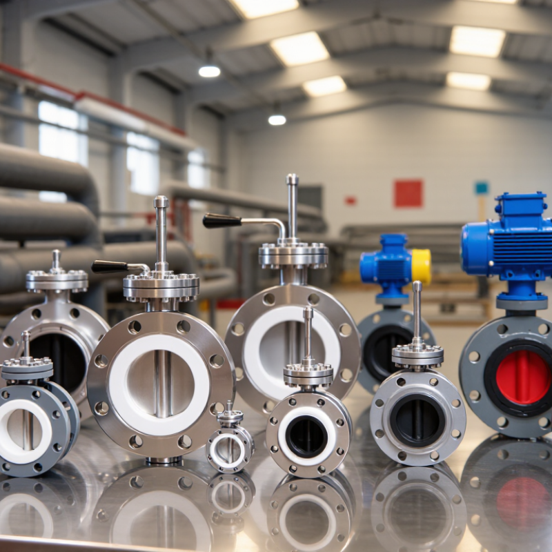
Choosing the butterfly valve type starts with the way it connects to the pipe. A wafer-style body sits between two flanges and is often suitable when space and weight are limited. A lug-style body uses threaded inserts around its perimeter; depending on the design, it can support removal of downstream piping while the upstream side remains connected. Flanged bodies bolt directly to matching pipe flanges and can make alignment more straightforward, but they need more room.
Check the installation, not just the catalog description. Measure the face-to-face space, confirm the flange standard, and consider how the valve will be serviced. A small mismatch can complicate installation. Body material matters too: cast iron may suit many general water duties, while stainless steel or other alloys may be needed for corrosive fluids. Verify compatibility with the actual fluid, temperature, and pressure, including the disc and seat materials. Those parts contact the process and can limit service life.
The flow and shutoff requirements help determine whether a concentric or offset design is appropriate. Concentric valves are common for general isolation, while offset designs may suit higher-pressure or more demanding duties, subject to the manufacturer’s limits. It is easy to focus on the body and overlook the seat. That’s a costly assumption. Review the piping layout and maintenance plan with a qualified valve or process specialist before finalizing the configuration.
Tip: Start with the fluid, not the catalog. For clean water, common elastomer seats may work well, but oils or solvents can swell or soften some materials. Check a compatibility chart for the exact fluid, concentration, and temperature. In wastewater, grit can abrade the seat over time. Small particles matter.
Tip: Consider the installation environment alongside the process fluid. Salt-laden air, outdoor rain, and washdown can corrode exposed valve parts. Stainless steel may help, but it is not automatically the right choice for every fluid or budget. Check the body, disc, stem, and fasteners—not just the seat. For hot service, confirm that every component tolerates the operating temperature and cycling.
Tip: Give the supplier real operating details. Include temperature swings, pressure, fluid concentration, and cleaning chemicals. A valve may perform well during steady operation and still fail after frequent cleaning or long periods unused. Not always obvious. Review product data and ask a qualified valve specialist to confirm suitability. I would avoid relying on a generic “chemical-resistant” label; it can hide important limits. Keep a note of the selected materials and the conditions they were checked against.
Typical service-temperature ranges vary by material grade, valve design, and manufacturer. Check chemical compatibility with the fluid and confirm the limits for the specific valve before selecting a material.
Tip: define the operating range before selecting a nominal diameter. Record minimum, normal, and peak flow, plus fluid temperature, density, and viscosity. Pipe size alone is not a valve size. A DN100 line carrying 40 m³/h may need a different disc opening than expected; verify capacity using Cv or Kv data and suitable sizing calculations. Leave enough control range, but avoid needless pressure loss.
Tip: check pressure and temperature together. Include maximum operating pressure, pump shutoff pressure, and possible surges. Then confirm the pressure-temperature rating against ASME B16.34 or the applicable valve standard. Pressure class numbers are not universal working pressures. Small detail, big consequence.
Tip: calculate capacity using actual fluid conditions and expected pressure drop. The U.S. Department of Energy’s Improving Pumping System Performance: A Sourcebook for Industry reports that pumping systems account for nearly 20% of global electricity demand and 25–50% of energy use in some industrial facilities. This is system-level context, not a guaranteed valve-savings figure; correct sizing can help limit excessive throttling losses. Check cavitation and noise limits, too. Calculations can look tidy. Field data may disagree.
| Tip | Selection factor | Practical guidance | What to verify |
|---|---|---|---|
| 1 | Define the duty | Record the fluid, normal and maximum flow, operating temperature, and minimum and maximum pressure. Include start-up, shutoff, and other transient conditions where relevant. | Use the actual operating range—not only the normal operating point—as the basis for selection. |
| 2 | Select the valve size | Start with the pipeline’s nominal diameter, but confirm the valve size by checking required flow capacity and pressure loss. A valve does not always need to match the line size. | Check the valve’s flow coefficient (Cv or Kv) at the expected opening and ensure the selected size will not cause excessive pressure drop or poor control. |
| 3 | Calculate flow capacity | For water in U.S. customary units, a common sizing relationship is Q = Cv × √(ΔP / SG), where Q is flow in gpm, ΔP is pressure drop in psi, and SG is specific gravity relative to water. | Use the valve’s published Cv data and account for fluid properties, opening angle, and the pressure drop available across the valve. Gas and steam require different sizing methods. |
| 4 | Check pressure and temperature | Choose a pressure class or rating that covers the maximum operating and design conditions. ASME Class 150 and Class 300 are class designations, not pressure ratings in psi. | Confirm the applicable pressure-temperature rating for the valve body, disc, seat, and trim materials; allowable pressure can decrease as temperature rises. |
| 5 | Match materials to the fluid | Select body, disc, stem, and seat materials for the fluid’s chemical compatibility, temperature, and service conditions. Water, seawater, oils, and corrosive chemicals may require different material combinations. | Review corrosion, erosion, solids, and elastomer compatibility. Confirm whether the seat material is suitable for the required temperature and shutoff duty. |
| 6 | Choose the connection and installation | Common configurations include wafer, lug, and flanged bodies. The choice depends on pipeline flanges, available space, maintenance needs, and whether the valve must be removed or isolated. | Check face-to-face dimensions, flange drilling, disc clearance, flow direction requirements, and whether the specific lug design permits end-of-line service. |
| 7 | Select operation and shutoff needs | Choose a lever, gear operator, or actuator according to valve size, operating frequency, required response, and available power. Specify whether the valve is for isolation, throttling, or both. | Confirm torque requirements, control signal or power supply, fail position where applicable, leakage class, and the valve’s suitability for continuous throttling. |
Tip 1: Match the actuator to the task. A manual lever suits occasional operation; frequent cycling or remote control may justify electric or pneumatic actuation. Check torque at the valve’s actual pressure differential, not just its nominal size. Tip 2: Confirm the interface. ISO 5211 covers actuator mounting dimensions, while API 609 addresses butterfly-valve design. Verify the required pressure class, materials, and end connections against the project specification. Standards are not interchangeable.
Tip 3: Compare the whole operating setup. Electric actuators need suitable power and controls; pneumatic units need reliable air supply and may require accessories. Tip 4: Ask how failure should look. Specify fail-open, fail-closed, or fail-in-place behavior where process safety requires it. Tip 5: Plan maintenance access. Leave room to inspect the stem, seals, actuator, and nearby pipework. Small detail, often missed.
Tip 6: Set a realistic inspection schedule based on cycling, fluid cleanliness, temperature, and leakage history. McKinsey’s predictive-maintenance analysis reports potential reductions of 30–50% in machine downtime across industrial settings; that is not a valve-specific guarantee, but it supports tracking condition rather than relying only on fixed intervals. Tip 7: Record baseline torque, stroke time, and leakage checks after commissioning. Trends can reveal wear early. Still, readings need context: a changing process can resemble a failing valve.
